Download Implementing a Software-Defined Datacenter.70-745.Prep4Sure.2018-11-09.30q.tqb
| Vendor: | Microsoft |
| Exam Code: | 70-745 |
| Exam Name: | Implementing a Software-Defined Datacenter |
| Date: | Nov 09, 2018 |
| File Size: | 2 MB |
How to open TQB files?
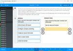
Files with TQB (Taurus Question Bank) extension can be opened by Taurus Exam Studio.
Purchase
Coupon: TAURUSSIM_20OFF
Discount: 20%
Demo Questions
Question 1
You need to configure the network settings for the SLB in the test environment.
Which two actions should you perform? Each correct answer presents part of the solution.
NOTE: Each correct selection is worth one point.
- Create a logical network that uses the Private VLAN networks option.
- Create a logical network that uses the One connected network option.
- Create a private VIP and IP address pool that uses the IP range 10.10.90.2 - 10.10.90.254. Create a public VIP and IP address pool that uses the IP range 10.10.20.2 – 10.10.20.254.
- Create a private VIP and IP address pool that uses the IP range 10.40.90.2 - 10.40.90.254. Create a public VIP and IP address pool that uses the IP range 10.40.20.2 – 10.40.20.254.
Correct answer: AD
Explanation:
References:https://blogs.technet.microsoft.com/larryexchange/2016/05/31/step-by-step-for-deploying-a-sdnv2-using-vmm-part-3/ References:
https://blogs.technet.microsoft.com/larryexchange/2016/05/31/step-by-step-for-deploying-a-sdnv2-using-vmm-part-3/
Question 2
You need to deploy the production SCVMM instance.
Which values should you supply for each installation option? To answer, select the appropriate options in the answer area.
NOTE: Each correct selection is worth one point.
Correct answer: To work with this question, an Exam Simulator is required.
Explanation:
When you install VMM you need to configure the VMM service to use either the Local System account or a domain account. If you specify a domain account, the account must be a member of the local Administrators group on the computer. References:https://docs.microsoft.com/en-us/system-center/vmm/plan-install?view=sc-vmm-1801#account-and-domain-requirements When you install VMM you need to configure the VMM service to use either the Local System account or a domain account. If you specify a domain account, the account must be a member of the local Administrators group on the computer.
References:
https://docs.microsoft.com/en-us/system-center/vmm/plan-install?view=sc-vmm-1801#account-and-domain-requirements
Question 3
You need to create the VM network for the development environment.
Which four actions should you perform in sequence? To answer, move the appropriate actions from the list of actions to the answer area and arrange them in the correct order.
Correct answer: To work with this question, an Exam Simulator is required.
Explanation:
To create a logical network 1. Open the Fabric workspace. 2. On the Home tab, in the Show group, click Fabric Resources. 3. In the Fabric pane, expand Networking, and then click Logical Networks. 4. On the Home tab, in the Create group, click Create Logical Network. The Create Logical Network Wizard opens. 5. On the Name page, do the following:* Enter a name and optional description for the logical network. For example, enter the name BACKEND, with the description Corporate network. Use for internal servers such as application and database servers. * If you have System Center 2012 SP1 or System Center 2012 R2, select check boxes as appropriate by using the table that follows. Otherwise, skip to the next numbered step in this procedure. Select one or more check boxes based on how you intend to use the VM networks that will be configured on top of this logical network. The following table provides guidelines:6. Click Next. 7. On the Network Site page, take the following steps. Note For guidelines for configuring network sites, see “Network sites” in Configuring Logical Networking in VMM Overview. If you do not need to configure network sites, on the Network Site page, click Next, and then click Finish to complete the wizard. 1. To create a network site, click Add. VMM automatically generates a site name that consists of the logical network name, followed by an underscore and a number. 2. Review the network site name and ensure that it is no longer than 64 characters. To change the default name, in the Network site name box, enter a new name for the network site. For example, enter the name BACKEND - Seattle. 3. Under Host groups that can use this network site, select the check box next to each host group to which you want to make the logical network available. For example, to make the BACKEND logical network available to the Seattle host group and all its child host groups, select the check box next to Seattle. 4. Under Associated VLANs and IP subnets, enter the VLANs and IP subnets that you want to assign to the network site. To enter VLAN and IP subnet information, click Insert row, click the field under VLAN or IP subnet, depending on what you want to configure, and then enter a VLAN, an IP subnet, or a subnet/VLAN pair. You can insert multiple rows. For example, add the IP subnet/VLAN pair that makes up the example BACKEND network in Seattle, as shown in the following table. Important In your test environment, make sure that you use VLANs and IP subnets that are available in your network. 5. Optionally, create additional network sites by clicking Add and repeating the process. 6. When you complete this step, click Next. 8. On the Summary page, review the settings, and then click Finish. The Jobs dialog box appears. Make sure the job has a status of Completed, and then close the dialog box. 9. Verify that the logical network appears in the Logical Networks and IP Pools pane. Also, if you added network sites, right-click the logical network, click Properties, click the Network Site tab, and verify that the intended network sites appear on the tab. References:https://technet.microsoft.com/en-us/library/gg610588(v=sc.12).aspx To create a logical network
1. Open the Fabric workspace.
2. On the Home tab, in the Show group, click Fabric Resources.
3. In the Fabric pane, expand Networking, and then click Logical Networks.
4. On the Home tab, in the Create group, click Create Logical Network.
The Create Logical Network Wizard opens.
5. On the Name page, do the following:
* Enter a name and optional description for the logical network.
For example, enter the name BACKEND, with the description Corporate network. Use for internal servers such as application and database servers.
* If you have System Center 2012 SP1 or System Center 2012 R2, select check boxes as appropriate by using the table that follows. Otherwise, skip to the next numbered step in this procedure.
Select one or more check boxes based on how you intend to use the VM networks that will be configured on top of this logical network. The following table provides guidelines:


6. Click Next.
7. On the Network Site page, take the following steps.
Note
For guidelines for configuring network sites, see “Network sites” in Configuring Logical Networking in VMM Overview. If you do not need to configure network sites, on the Network Site page, click Next, and then click Finish to complete the wizard.
1. To create a network site, click Add.
VMM automatically generates a site name that consists of the logical network name, followed by an underscore and a number.
2. Review the network site name and ensure that it is no longer than 64 characters. To change the default name, in the Network site name box, enter a new name for the network site.
For example, enter the name BACKEND - Seattle.
3. Under Host groups that can use this network site, select the check box next to each host group to which you want to make the logical network available.
For example, to make the BACKEND logical network available to the Seattle host group and all its child host groups, select the check box next to Seattle.
4. Under Associated VLANs and IP subnets, enter the VLANs and IP subnets that you want to assign to the network site. To enter VLAN and IP subnet
information, click Insert row, click the field under VLAN or IP subnet, depending on what you want to configure, and then enter a VLAN, an IP subnet, or a subnet/VLAN pair. You can insert multiple rows.
For example, add the IP subnet/VLAN pair that makes up the example BACKEND network in Seattle, as shown in the following table.

Important
In your test environment, make sure that you use VLANs and IP subnets that are available in your network.
5. Optionally, create additional network sites by clicking Add and repeating the process.
6. When you complete this step, click Next.
8. On the Summary page, review the settings, and then click Finish.
The Jobs dialog box appears. Make sure the job has a status of Completed, and then close the dialog box.
9. Verify that the logical network appears in the Logical Networks and IP Pools pane. Also, if you added network sites, right-click the logical network, click Properties, click the Network Site tab, and verify that the intended network sites appear on the tab.
References:
https://technet.microsoft.com/en-us/library/gg610588(v=sc.12).aspx
Question 4
You must upgrade all Hyper-V clusters that support an upgrade.
Which 2 clusters can you upgrade?
- Atl-cluster
- Det-cluster
- Tor-cluster
- Dal-cluster
Correct answer: BD
Explanation:
References:https://docs.microsoft.com/en-us/system-center/vmm/hyper-v-rolling-upgrade?view=sc-vmm-1807 References:
https://docs.microsoft.com/en-us/system-center/vmm/hyper-v-rolling-upgrade?view=sc-vmm-1807
Question 5
You manage Microsoft System Center Virtual Machine Manager (SCVMM). You plan to implement a software load balancer (SLB) Multiplexer (MUX).
You need to configure the Microsoft Hyper-V host servers to host the MUX.
What should you do?
- Configure Windows Server Gateway.
- Install the SLB Host Agent on each Hyper-V host.
- Configure virtual machine resource metering.
- Configure a Remote Access Service gateway.
Correct answer: B
Explanation:
You can use System Center to deploy SLB MUXs and to install SLB Host Agents on computers that are running Windows Server 2016 Technical Preview and Hyper-V. When you deploy SLB, you must use System Center, Windows PowerShell, or another management application to deploy the SLB Host Agent on every Hyper-V host computer. References:https://technet.microsoft.com/en-US/library/mt632286.aspx You can use System Center to deploy SLB MUXs and to install SLB Host Agents on computers that are running Windows Server 2016 Technical Preview and Hyper-V.
When you deploy SLB, you must use System Center, Windows PowerShell, or another management application to deploy the SLB Host Agent on every Hyper-V host computer.
References:
https://technet.microsoft.com/en-US/library/mt632286.aspx
Question 6
You administer the Microsoft System Center Virtual Machine Manager (SCVMM) infrastructure for an organization. You deploy a software load balancer (SLB).
You need to create a health probe to verify that the VIP pool members are healthy.
Which health probe response code should you identify?
- 200
- 202
- 300
- 302
Correct answer: A
Explanation:
An HTTP health probe should return a response code of 200 to indicate a healthy status. References:https://docs.microsoft.com/en-us/windows-server/networking/sdn/manage/configure-slb-and-nat An HTTP health probe should return a response code of 200 to indicate a healthy status.
References:
https://docs.microsoft.com/en-us/windows-server/networking/sdn/manage/configure-slb-and-nat
Question 7
You manage virtual machine (VM) workloads in an environment that includes the following objects:
- an IP address pool
- a software load balancer (SLB) object
- an SLB rule
- a public VIP address
You monitor network traffic logs and observe that a VM does not service requests for the VIP address.
You need to configure the virtual network so that traffic is not sent to a VM that is unavailable.
What should you do?
- Add a health probe. Change the SLB configuration to use the health probe. Redeploy the SLB rule.
- Add support for HTTP keep-alive. Change the SLB configuration to Enable keep-alive. Redeploy the SLB rule.
- Change the VM IP addresses to public IP addresses. Redeploy the SLB rule.
- Change the protocol for the SLB rule to UDP. Redeploy the SLB rule.
Correct answer: A
Explanation:
References:https://docs.microsoft.com/en-us/windows-server/networking/sdn/manage/configure-slb-and-nat References:
https://docs.microsoft.com/en-us/windows-server/networking/sdn/manage/configure-slb-and-nat
Question 8
You manage Microsoft System Center Virtual Machine Manager (SCVMM).
You need to block specific packets on the virtual switch.
Which two types of virtual switch extensions can you use? Each correct answer presents a complete solution.
NOTE: Each correct selection is worth one point.
- capturing extensions
- forwarding extensions
- monitoring extensions
- filtering extensions
Correct answer: BD
Explanation:
A Hyper-V extensible switch filtering extension can inspect, modify, and insert packets into the extensible switch data path. Based on extensible switch port and switch policy settings, the extension can drop a packet or exclude its delivery to one or more destination ports. A forwarding extension has the same capabilities as a filtering extension, but is responsible for performing the core packet forwarding and filtering tasks of the extensible switch. References:https://docs.microsoft.com/en-us/windows-hardware/drivers/network/overview-of-the-hyper-v-extensible-switch A Hyper-V extensible switch filtering extension can inspect, modify, and insert packets into the extensible switch data path. Based on extensible switch port and switch policy settings, the extension can drop a packet or exclude its delivery to one or more destination ports.
A forwarding extension has the same capabilities as a filtering extension, but is responsible for performing the core packet forwarding and filtering tasks of the extensible switch.
References:
https://docs.microsoft.com/en-us/windows-hardware/drivers/network/overview-of-the-hyper-v-extensible-switch
Question 9
You manage a Microsoft Hyper-V host server that has several high-speed physical network adapters.
You need to attach a physical network adapter directly to a virtual machine (VM).
What should you do first?
- Assign the adapter to the VM.
- Disable the adapter on the Hyper-V host.
- Install the device driver on the Hyper-V host.
- Install the device driver on the VM.
Correct answer: B
Question 10
You deploy Microsoft System Center Virtual Machine Manager (SCVMM) and System Center Operations Manager (SCOM). You integrate SCVMM with SCOM.
You need to view the reports for SCVMM.
What are two possible ways to achieve the goal? Each correct answer presents a complete solution.
- Launch the SCOM console.
- Launch the SCVMM console.
- Run the Windows PowerShell cmdlet Get-SCOMMonitor.
- Run the Windows PowerShell cmdlet Get-SCOMReportingSetting.
- View the Reporting server website for SCOM.
Correct answer: AE
Explanation:
You can view reports in the Reporting workspace in System Center Operations Manager, or by using a web browser and entering this address: http://ReportingServerName:port/reports.References:https://docs.microsoft.com/en-us/system-center/vmm/monitor?view=sc-vmm-1801 You can view reports in the Reporting workspace in System Center Operations Manager, or by using a web browser and entering this address: http://ReportingServerName:port/reports.
References:
https://docs.microsoft.com/en-us/system-center/vmm/monitor?view=sc-vmm-1801
HOW TO OPEN VCE FILES
Use VCE Exam Simulator to open VCE files
HOW TO OPEN VCEX FILES
Use ProfExam Simulator to open VCEX files
ProfExam at a 20% markdown
You have the opportunity to purchase ProfExam at a 20% reduced price
Get Now!